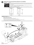
Bulletin 592 E1 Plus Overload Relay Application and Installation
(Cat 592-EE _ _ ; 592S-EE _ _ )
To prevent electrical shock, disconnect from power source before installing or servicing. Install in suitable enclosure. Keep
free from contaminants.
AVERTISSEMENT Avant le montage et la mise en service, couper l'alimentation secteur pour éviter toute décharge. Prévoir une mise en coffret
ou armoire appropriée. Protéger le produit contre les environnements agressifs.
Desconéctese de la corriente eléctrica, antes de la instalación o del servicio, a fin de impedir sacudidas eléctricas. Instálelo en
WARNUNG
una caja apropiada. Manténgalo libre de contaminantes.
WARNING
NEMA Size 0, 1, 2, 3, 4
(3 Phase)
L1
95
L2
96
T1
97
T2
NEMA Size 0, 1, 2, 3
(Single Phase)
L3
L1
95
98
L2
96
L3
97
T1
T3
98
T3
MOTOR
MOTOR
Bulletin 509 Size 0, 1, 2
To Replace Existing Overload Relay
- Disconnect power wires and control wires from overload relay.
- Remove the two screws that secure the overload relay to the mounting plate.
- Loosen, but do not remove the screws that connect the overload relay terminals to the contactor terminals.
- Lift overload relay away from mounting plate and slide away from contactor to remove.
NEMA Size 0, 1
NEMA Size 2
4
23 lb-in
(2.6 N•m)
35 lb-in
(4.0 N•m)
3
1
16 lb-in
(1.8 N•m)
2
PN-68713
DIR 10000094347 (Version 02)
Printed in U.S.A.
12 lb-in
(1.4 N•m)
Bulletin 509 Size 3, 4
To Replace Existing Overload Relay
- Disconnect power wires and control wires from overload relay.
- Remove the two screws that secure the overload relay mounting plate to the back of the contactor mounting plate.
- Remove the screws that connect the overload relay terminals to the contactor terminals.
- Separate the overload relay from the contactor and remove.
12 lb-in
(1.4 N•m)
Bulletin 509
Size 3
140 lb-in
(16 N•m)
3
4
1
2
Bulletin 509
Size 4
200 lb-in
(23 N•m)
12 lb-in
(1.4 N•m)
30 lb-in
(3.4 N•m)
5
3
200 lb-in
(23 N•m)
4
1
2
PN-68713
DIR 10000094347 (Version 02)
(2)
30 lb-in
(3.4 N•m)
E1 Plus Features
Caractéristiques du E1 Plus
Características del E1 Plus
Push to Reset
Enfoncer pour réinitialiser
Presione para reiniciar
Push To Test
Enfoncer pour tester
Presione para probar
Rotate to Manually Trip
Faire pivoter pour déclencher manuellement
Rotar para disparar manualmente
RESET MODE
A
M
TRIP CLASS
10
15
20
30
A = Automatic/Manual Reset Mode
A = Mode de réinitialisation automatique/manuel
A = Modo de reinicio automático/manual
M = Manual Reset Mode
M = Mode de réinitialisation manuel
M = Modo de reinicio manual
Trip Indicator Window
Yellow indicator not visible: Not Tripped.
Yellow indicator visible: Tripped.
Fenêtre d'indicateur de déclenchement
Reset Bar Removed for Clarity
Indicateur jaune non visible : pas de déclenchement
Barre de réinitialisation supprimée pour
Indicateur jaune visible : déclenchement
plus de clarté
Ventana indicadora de disparo
Se eliminó la barra de reinicio para
Indicador amarillo no visible: No disparado
mayor claridad
Indicador amarillo visible: Disparado
S.F. _ _
FLA _ _
S.F. < 1.15
= .9 X FLA
S.F. ≥ 1.15
= 1 X FLA
Y
=
FLA
1.73
Selectable Trip Class
Classe de déclenchement
sélectionnable
Clase de disparo seleccionable
To adjust trip current, turn dial until the desired current is
aligned with the pointer. Trip rating is 120% of dial setting.
Pour régler l'intensité de déclenchement, tournez le cadran jusqu'à
ce que le pointeur soit sur l'intensité voulue. La valeur nominale
de déclenchement est de 120% du réglage cadran.
Para ajustar la corriente del disparo, gire el dial hasta que la corriente
deseada esté alineada con la marca . La capacidad nominal del
disparo es el 120% del posicionamiento del dial.
Do not use automatic reset mode in applications where unexpected automatic restart of the motor can cause injury to persons or
damage to equipment.
AVERTISSEMENT N'utilisez pas le mode Remise à zéro automatique dans les applications où un redémarrage automatique inattendu du moteur pourrait
provoquer des blessures personnelles ou des dégâts matériels.
No use el modo de restablecimiento automático donde un restablecimiento automático del motor inesperado pueda causar heridas a
ADVERTENCIA
personas o daño al equipo.
WARNING
Rated Insulation Voltage (Ui):
Rated Operational Voltage(Ue) IEC/UL:
Rated Operating Frequency:
Main Connections
Raccordements Principale
Conexiones Principales
Terminal Screw
1x
2x
Control Connections
Bornes de Commande
Conexiones de Control
690V AC
690V AC / 600V AC
50 / 60 Hz
Size 0 - 2
Size 3
Size 4
M5
M8
--
1x
14 … 6 AWG
22 lb-in
12 … 6 AWG
30 lb-in
2x
12 … 1 AWG
35 lb-in
6 … 2 AWG
35 lb-in
6 … 4/0 AWG
275 lb-in
#2
--
--
1 x 6 mm
--
--
--
4 mm
5/16”
Rated Insulation Voltage (Ui):
Rated Operational Voltage (Ue) IEC / UL:
Rated Operational Current (Ie):
690V AC
690V AC / 600V AC
B600 N.O. / N. C.
M3
Terminal Screw
24 … 10 AWG
5 lb-in
24 … 10 AWG
5 lb-in
1x
2x
#1
0.6 x 3.5 mm
PN-68713
DIR 10000094347 (Version 02)
1x
(3)
Trip Curve
Courbe de déclenchement
Curva de disparo
HOT START
DEMARRAGE A CHAUD
ARRANQUE EN CALIENTE
COLD START
DEMARRAGE A FROID
ARRANQUE EN FRIO
Class 10
Class 20
Class 15
Class 30
1000
1000
1000
1000
100
100
100
100
10
10
10
10
1
1
1
1
0.1
0.1
1
8
0.1
1
8
0.1
1
8
1
Multiple of FLA
Intensités pleine charge multiples
Múltiplo de FLA
Short Circuit Ratings
Table 1 Standard Fault Short Circuit Ratings per UL508 and CSA 22.2 No.14
E1 Plus Cat. No.
Max. available fault Max. voltage
current (kA)
(V)
S.C.P.D.
592
Suitable for
use with
fuses only
EEBC
1
EECC, EEDC, EEEC, EEFC, EEPC, EERC
592, 592S EESC, EETC
592
600
5
EEFD, EEGD, EEUD
EEHE
Not restricted
to fusing only
10
10
Table 2 High Fault Short Circuit Ratings per UL508 and CSA 22.2 No.14
MAX.
available
fault
current
(KA)
MAX.
voltage
(V)
00, 0, 1
100
EECC, EEDC,
EEEC
0
100
EECC, EEDC,
EEEC, EEFC
1
100
EEEC, EEFC
2
100
EEFD, EEGD
3
100
EEHE
4
100
600
240
480
600
240
480
600
240
480
600
240
480
600
240
480
600
E1 Plus Cat. No.
EEBC
592
PN-68713
DIR 10000094347 (Version 02)
Contactor
Size
Max. UL Class R or
Class J fuse (A)
(4)
R
J
30
30
30
60
30
30
100
60
60
200
100
100
400
200
200
6
30
30
30
100
50
50
200
100
100
350
200
200
500
400
400
Circuit Breaker / Limiter
FDB 3025/LFB 3070R
FDB 3025/LFB 3070R
FDB 3050/LFB 3070R
FDB 3035/LFB 3070R
FDB 3100/LFB 3150R
FDB 3150/LFB 3150R
FDB 3125/LFB 3150R
FDB 3100/LFB 3150R
FDB 3150/LFB 3150R
FDB 3150/LFB 3150R
8
NEMA Size 0, 1, 2, 3, 4
NEMA Taille 0, 1, 2, 3, 4
NEMA Tamaño 0, 1, 2, 3, 4
B
C
D
L
E
F
A
G
"H"
Reset Area
Reset Button
Travel: .10 [2.5]
"J"
Reset Area
K
NEMA Size
A
7.6
(194)
B
3.6
(90.4)
C
1.8
(45.2)
D
0.4
(9.8)
E
0.3
(7.1)
F
5.0
(126)
G
7.1
(179)
H
J
1.2
1.8
(30.7) (44.8)
K
2.8
(70)
L
4.4
(113)
M
4.2
(108)
9.2
(233)
3.9
(100)
2.0
(50)
0.4
(9.8)
0.3
(7.1)
6.0
(153)
8.6
(219)
1.2
1.8
3.2
(30.7) (44.8) (80.1)
4.7
(118)
4.4
(112)
2
in
(mm)
in
(mm)
3
in
(mm)
13.3
(337)
6.1
(156)
2.75
(70)
0.78
(20)
0.31
(7.9)
9.27
(235)
8.66
(220)
1.8
1.7
(43.4) (44.8)
5.5
(140)
5.9
(150)
6.06
(154)
4
in
(mm)
16.5
(419)
7.4
(187)
3.7
(94)
0.95
(24)
0.38
(9.6)
10.8
(274)
15
(380)
1.8
(44.8)
1.2
(30.7)
6.3
(160)
7.8
(198)
7.84
(199)
0-1
PN-68713
DIR 10000094347 (Version 02)
M
(5)
PN-68713
DIR 10000094347 (Version 02)
Printed in U.S.A.
">