DEUTSCH
WICHTIG
- Wenn Sie Informationen zur Installation,
zum Betrieb oder zur Wartung des Produkts
benötigen, die nicht in dieser Anleitung enthalten sind, wenden Sie sich mit Ihrer Frage an
einen autorisierten Vertriebspartner von Carlo Gavazzi. Die Informationen in diesem Dokument sind nicht
bindend hinsichtlich der Produktgewährleistung. - Die
Installation und Wartung dieses Geräts darf nur von qualifiziertem Fachpersonal durchgeführt werden.
- Betreiben Sie das SSR stets innerhalb der Spezifikation,
da es andernfalls zu Fehlfunktionen, Beschädigungen
oder Brandgefahr kommen kann.
- Für die Verwendung in einer Umgebung mit dem Verschmutzungsgrad 2.
- Sollte das Gerät nicht gemäss der Herstellerangaben
verwendet werden, könnte der vom Gerät vorgesehene
Schutz beeinträchtigt werden.
- Sicherstellen, dass die Anschlüsse korrekt ausgeführt
worden sind, um Fehlfunktionen oder Beschädigungen
des Geräts zu vermeiden.
- Folgen Sie den PROFINET Richtlinien für die Ethenetverkablung. Mindestens Cat 5e geschirmte Verkablung.
Element
Function
Element
Funktion
Elemento
Función
Element
Funktion
Us+ Us-
+24VDC
Us+ Us-
+ 24VDC
Us+ Us-
+24VDC
Us+ Us-
+24VDC
Push
button
Press between 2 to 5s for
communication check
Press for 3s during power-up for
Auto-Addressing (Fig. 1. Fig. 2)
Push
button
Tryk mellem 2 - 5s for kommunikationskontrol Tryk på 3s under opstart til
Auto-adressering (Fig. 1. Fig. 2)
Push
button
Push
button
ON LED
Supply: ON
ON LED
Forsyning ON
Pulsar entre 2 y 5 segundos para comprobar la comunicación. Pulsar durante 3 segundos al encender para direccionamiento automático (Fig. 1. Fig. 2)
Alimentación ON
BUS LED
Aktiver kommunikation med
RG..Ns
ON LED
Drücken Sie zwischen 2 und 5s zum
überprüfen
der
Kommunikation.
Drücken Sie für die Autokonfiguration
den Taster 3s während des Bootvorgangs (Fig. 1. Fig. 2)
Versorgung EIN
SF LED
System fejl
Comunicación en curso con
relés RG..N
ON LED
BUS LED
BUS LED
Kommunikation aktiv mit den RG..Ns
BF LED
Bus fejl
SF LED
Fallo del sistema
SF LED
System Fehler
Ongoing communication with
RG..Ns
BUS LED
SF LED
System Fault
BF LED
Bus Fault
BF LED
Fallo del BUS
BF LED
BUS Fehler
ALARM LED
ALARM: ON
ALARM LED
Alarm ON
ALARM LED
Alarma ON
ALARM LED
Alarm
Link / RX/TX
LEDs
Ongoing ethernet connection
Link / RX/TX
LEDs
Aktuel kommunikation med
hovedkontrolenheden
Link / RX/TX
LEDs
Conexión Ethernet en curso
Link / RX/TX
LEDs
Ethernet aktiv
X1, X2
Profinet ports
X1, X2
Profinet ports
X1, X2
Puertos Profinet
X1, X2
PROFINET Anschluß
BUS
Micro-USB port for internal bus
BUS
Micro USB port for intern bus
BUS
Puerto micro USB para bus interno
BUS
Mikro USB-Schnittstelle für den
internen Bus
MAC
address
Device MAC address. Increment
by 1 and 2 for MAC addresses
of X1 and X2
MAC
address
Enheds MAC-adresse Forøgelse
med 1 og 2 for MAC-adresser på
X1 og X2
MAC
address
Dirección dispositivo MAC. Aumentar en 1 y 2 para direcciones
MAC X1 y X2
MAC
address
Geräte MAC Adresse um 1 und 2
erhöhen für MAC Adresse von X1
und X2
Connection diagram | Tilslutningsdiagrammer | Diagrama de conexiones |
Anschlussdiagramme | Diagramme de raccordement | Diagramma delle connessioni | Схема подключения | 连接图
24 VDC
NRG
BUS chain 1
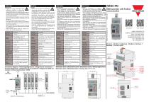
NRGC-PN
NRG Controller with Profinet
communication
Datasheet
User Manual
CARLO GAVAZZI LTD
BLB042, Bulebel Industrial Estate
Zejtun ZTN 3000, Malta
www.gavazziautomation.com
info@gavazziautomation.com
info: +356 23601.100
fax: +356 23601.111
Structure | Struktur | Estructura | Struktur | Structure |
Struttura | Состав | 结构体
Us+ UsMAC
address
Us-
Us+
MAC 00:1
9:EE:04:A
E
PUSH
button
ON
Dimensions (mm) | Dimensioner (mm) | Dimensiones (mm) | Abmessungen (mm) |
Dimensions (mm) | Dimensioni (mm) | Размеры (мм) | 尺寸(mm)
ON LED
SF
SF LED
BF
ALAR
M
BF LED
NRGC - PN
ESPAÑOL
IMPORTANTE
- En caso de necesitar información sobre la instalación funcionamiento o
mantenimiento del producto que no
venga reflejada en este documento
de instrucciones, deberá consultar con su distribuidor o con una oficina de Carlo Gavazzi. La
información de este documento no se considera
vinculante con la garantía del producto.
- Solo personal autorizado y cualificado puede
instalar y realizar labores de mantenimiento de
este equipo.
- Para uso en entornos con grado de contaminación 2.
- Si el equipo se utiliza de forma no especificada
por el fabricante, la protección dotada al equipo
puede resultar dañada.
- Asegúrese de que las conexiones relevantes se
han llevado a cabo correctamente, con el fin de
evitar un funcionamiento incorrecto o que el equipo resulte dañado.
- Seguir la guía de cableado Profinet para conexión
Ethernet. Mín. cable apantallado de Cat. 5e
7680674-00
DANSK
VIGTIGT
- Såfremt du har behov for oplysninger
vedrørende installation, betjening eller
vedligeholdelse af produktet, der ikke
er indeholdt i dette dokument, bedes du rette
henvendelse til en autoriseret Carlo Gavazzirepræsentant. Oplysningerne i dette dokument er
ikke bindende i henhold til nogen produktgaranti.
- Det er kun autoriseret personale, der må installere og udføre vedligeholdelse på dette udstyr.
- Til brug i forureningsgrad II-miljø.
- Hvis instrumentet skal anvendes på en måde, der
ikke er beskrevet af producenten, kan beskyttelsen af instrumentet blive svækket.
- Kontrollér, at tilslutningerne er foretaget korrekt
for at undgå fejlfunktioner eller beskadigelse af
instrumentet.
- Følg Profinet kabelføringsguider for Ethernet-forbindelse. Min. Cat 5e afskærmet kabel
NRGC_PN_inst_leaf_04_20
ENGLISH
IMPORTANT
- Should you require information about
installation, operation or maintenance
of the product that is not covered in this
instruction document you should refer the matter to
an authorised Carlo Gavazzi representative. The information in this document is not considered binding
on any product warranty.
- Only authorised and qualified personnel should be
allowed to install and perform maintenance on this
equipment.
- For use in Pollution Degree 2 Environment.
- If the instrument is used in a manner not specified by
the producer, the protection provided by the instrument may be impaired.
- Make sure that the connections are correctly carried
out in order to avoid any malfunctioning or damage
to the instrument.
- Follow Profinet cabling guides for ethernet connection. Min. Cat 5e shielded cable
ALARM
LED
RG..N
RG..N RG..N RG..N RG..N
X2
BUS
Link / RX / TX LEDs
Us-
NRGC-PN
Max. 32
RG..Ns in one
BUS chain
Us+
BUS LED
Us-
Us+
ON
SF
ALARM
LINK
BUS
ON
X1, X2
SF
ALARM
Profinet
Device
NRGC-PN or Profinet Device
RGN-TERMRES
X1
LINK
Internal BUS
RCRGN-xx-2
X2
NRGC - PN
BF
RX/TX
Profinet
controller
(PLC)
RX/TX
X1
X2
NRGC - PN
BF
BUS
BUS
FRANCAIS
РУССО
ITALIANO
IMPORTANT
- Pour plus amples détails concernant l’installation, le fonctionnement ou la maintenance du
produit et n’apparaissant pas dans cette fiche
technique, consulter un concessionnaire agréé Carlo
Gavazzi. Les informations contenues figurant dans ce
document ne constituent aucune obligation de garantie de
quelconque nature.
- Seul un personnel autorisé et qualifié est habilité à installer et à effectuer des opérations de maintenance sur ce
produit.
- Pour exploitation en environnement de degré de pollution
2.
- Si l’appareil est utilisé dans des conditions différentes de
celles spécifiées par le fabricant, le niveau de protection
prévu par l’instrument peut être compromis.
- S’assurer que les connexions sont réalisées correctement dans le but d’éviter toutes dysfonctionnements ou
détérioration de l’appareil.
- Suivez les guides de câblage Profinet pour la connexion
Ethernet. Câble blindé Cat 5e mini.
ВАЖНО
IMPORTANTE
- Если Вам требуется информация
- Se avete bisogno di informazioni su instal- по электромонтажу, эксплуатации
lazione, funzionamento o manutenzione
- или обслуживанию изделия, не содержащаяся
del prodotto non riportate in questo docu- в настоящем Руководстве, обратитесь с
mento è necessario sottoporre la questioВашим вопросом к местному авторизованному
ne ad un rappresentante autorizzato Carlo Gavazzi.
представителю Carlo Gavazzi. Информация
Le informazioni contenute in questo documento non
в этом документе не считается связанной с
sono da considerare vincolanti per alcuna garanzia
любыми гарантиями на изделие.
sul prodotto.
- L’installazione e la manutenzione di questo dispositi- - Только авторизованный и квалифицированный
персонал имеет право установки и обслуживания
vo devono essere effettuate da personale autorizzato
данного оборудования.
e qualificato.
- Для применения при Степени Загрязнения 2.
- Per l’impiego in grado di inquinamento 2.
- Qualora l’apparecchio venisse usato in un modo non - При применении прибора способом, отличным от
указанного изготовителем, возможно ухудшение
specificato dal costruttore, la protezione prevista
защиты, предоставляемой прибором.
dall’apparecchio potrebbe essere compromessa.
что
соединения
выполнены
- Assicurarsi che le connessioni previste siano esegui- - убедитесь,
правильно, во избежание неполадок или
te correttamente al fine di evitare qualsiasi malfunzioповреждения прибора.
namento o danneggiamento dello strumento.
подключения
к
сети
Ethernet
- Seguire le indicazioni di cablaggio Profinet per la - Для
руководствуйтесь указаниями по прокладке
connessione Ethernet. Min. Cavo schermato Cat 5e
кабеля Profinet. Минимальное требование:
экранированный кабель кат. 5e
简体中文
重要事项
-如果您需要本说明文档中 未涵
盖的产品的安装、操作或 维护
等
-相关信息,请咨询 Carlo Gavazzi 授权
代表。本文档中的信息 对任何产
-品保修均无约束力。
-只允许经过授权的合格人员 安装和维护
本设备
-适用于 2 度污染环境
-如果没有按照制造商的要求去操作,设
备的保护功能可能会失效。维护:为了
避免任何故障或者损坏仪器,请确保接
线正确。
-遵循Profinet以太网连接布线规范,最
低Cat.5e类屏蔽线缆
Element
Fonction
Elemento
Funzione
Элемент
Функция
基本要素
功能
Us+ Us-
+24VDC
Us+ Us-
+24VDC
Us+ Us-
+24VDC
Us+ Us-
+24VDC
Push
button
Нажимайте от 2 до 5 с для
проверки связи. Нажимайте 3 с
во время включения питания для
автоматической адресации (Fig. 1.
Fig. 2)
ON LED
电源ON
ON LED
Питание ВКЛ.
BUS LED
正在与RG…Ns通讯
BUS LED
Осуществляется связь с RG..Ns
SF LED
系统故障
SF LED
Ошибка системы
BF LED
总线错误
BF LED
Ошибка шины
ALARM LED
报警 ON
ALARM LED
Сигнал тревоги ВКЛ.
Link / RX/TX
LEDs
Идет подключение к Ethernet
Link / RX/TX
LEDs
正在进行以太网连接
X1, X2
Порты Profinet
X1, X2
Profinet 端口
Push
button
Appuyez entre 2 et 5s pour vérifier la
communication Appuyez pendant 3 s
pendant la mise sous tension pour l’adressage automatique (Fig. 1. Fig. 2)
ON LED
Alimentation ON
BUS LED
Communication en cours avec
RG..Ns
SF LED
Push
button
ON LED
Premere tra 2 - 5 secondi per il
controllo della comunicazione
Premere per 3 secondi durante
l’accensione per l’indirizzamento
automatico (Fig. 1. Fig. 2)
Alimentazione ON
按2-5秒进行通信检查
在通电期间按3秒进行自动配置
Push
button
1. Fig. 2)
(Fig.
FIG. 1
BUS LED
In comunicazione con RG..Ns
Défaut système
SF LED
Errore di sistema
BF LED
Défaut BUS
BF LED
Errore di BUS
ALARM LED
Alarme ON
ALARM LED
Allarme ON
Link / RX/TX
LEDs
Connexion Ethernet en cours
Link / RX/TX
LEDs
Connessione ethernet in corso
X1, X2
Ports Profinet
X1, X2
Porte Profinet
BUS
Port micro USB pour bus interne
BUS
Porta micro USB per bus interno
BUS
Микро-USB порт для
внутренней шины
BUS
用于内部总线的微型USB端口
MAC
address
Incrément de 1 et 2 de l’adresse
MAC de l’appareil pour les
adresses MAC de X1 et X2
MAC
address
Incremento dell’indirizzo MAC
del dispositivo di 1 e 2 per gli
indirizzi MAC di X1 e X2
MAC
address
Увеличение значения MACадреса устройства на 1 и 2 для
MAC-адресов X1 и X2
MAC
address
设备MAC地址增加1和2以对应
MAC地址的X1和X2
Mounting | Montering| Montaje | Befestigung | Montage | Montaggio |
Монтаж | 安装
Us+, Us-:
Use 60/75oC copper (Cu) conductors
0.2 - 2.5 mm²
0.5 - 1.0 mm²
26 - 12 AWG
X1, X2 :
x2 RJ45 shielded plugs | x2 RJ45 skærmede stik | x2 Conexiones RJ45 apantalladas | Abgeschirmter x2 RJ45-Stecker | x 2 Connecteurs blindés RJ45 | x2 Spine
schermate RJ45 | 2 шт. RJ45 Экранированные штекеры | x2 RJ45 屏蔽插头
BUS: RCRGN-xx-2
- Mounting on DIN rail
- Montage på DIN-skinne
- Montaje a carril DIN
- Befestigung auf der DIN-Schiene
- Montage sur rail DIN
- Montaggio su guida DIN
- Монтаж на DIN-рейку
- 安装于 DIN 导轨上
- Push to lock
- Pres for at låse
- Empujar para bloquear
- Push-to-Lock Taste
- Pousser pour vérouiller
- Premi per bloccare
- Утопите до защелкивания
- 推入锁定
- Dismounting from DIN rail
- Afmontering fra DIN-skinne
- Desmontaje a carril DIN
- Demontagevonder DIN-Schiene
- Dépose d’un SSR monté sur
rail DIN
- Smontaggio da guida DIN
- Демонтаж с DIN-рейки
- 从 DIN 导轨上拆除
RGN-TERMRES :
To be plugged on the last RG..N on the BUS chain
Tilsluttes den sidste RG..N på BUS-strengen
Debe conectarse en el último RG..N de la cadena del BUS
Abschluss zum Aufstecken auf den letzten RG..N des BUS-Systems
Doit être raccordé sur le dernier RG…N connecté sur le BUS
Da collegare sull’ultimo RG..N sulla catena BUS
Присоединить к последнему RG..N шины
应插接到总线链上最后一个 RG..N
FIG. 2
Auto-addressing of RG..Ns is automatically done on start up. This step is only
required if bus chain configuration is modified. Refer to User Manual for further
info.
FIG. 1 - Hold blue button during power up.
FIG. 2 - Release when Alarm LED: ON.
Terminations | Termineringer | Terminales | Anschlüsse |Terminations |
Terminali | Клеммы | 端接
0.2 - 2.5 mm²
22 - 14 AWG
X = 12 - 13 mm
Auto-addressing of internal bus | Auto-adressering af intern bus | Direccionamiento automático del bus interno |
Auto Adressierung des internen Bus | Adressage automatique du bus interne | Indirizzamento automatico del bus
interno | Автоматическая адресация внутренней шины |
内部总线自动寻址
Auto-adressering af RG..Ns udføres automatisk ved opstart. Dette trin er kun
påkrævet, hvis der ændres på bus konfigurationen.
FIG. 1 - Hold den blå knap nede under opstart.
FIG. 2 - Slip når alarm-LED: TIL.
El auto-direccionamiento de los relés RG..N se lleva a cabo automáticamente al
realizar la conexión. Este paso solo se necesita si se modifica la configuración
de la cadena de bus.
FIG.1 – Mantener el botón azul durante el encendido.
FIG. 2 – Soltar el botón cuando el LED de alarma esté encendido.
Automatische Adressierung is erforderlich sobald die Konfiguration des internen
Bus verändert wird. Siehe Bedienungsanleitung für weitere Informationen.
FIG. 1 - Halten Sie den blauen Taster gedrückt während des Bootvorgangs.
FIG. 2 - Lassen Sie den Taster los wenn Alarm leuchtet.
L’adressage des RG..Ns se fait automatiquement à la mis sous tension. Cette
étape n’est requise que si la configuration du bus est modifiée.
FIG. 1 - Maintenez le bouton bleu enfoncé pendant la mise sous tension.
FIG. 2 - Relâcher lorsque la LED d’alarme s’allume.
L’indirizzamento automatico di RG..Ns viene eseguito automaticamente
all’avvio. Questo passaggio è necessario solo se viene modificata la
configurazione della catena bus.
FIG. 1 - Tenere premuto il pulsante blu durante l’accensione.
FIG. 2 - Rilasciare quando LED di allarme: ON.
Автоматическая адресация RG..Ns выполнена автоматически при запуске.
Этот шаг требуется только в случае изменения цепочечной конфигурации
шины. Подробнее см. в руководстве пользователя.
FIG. 1 – Удерживайте нажатой синюю кнопку во время включения питания
FIG. 2 – Отпустите, когда светодиодный индикатор тревоги: ВКЛ.
系统开启时地址将自动分配给RG..N固态继电器。这个步骤只有当总线配置被调整后才需
要执行。
FIG. 1-通电时按住蓝色按钮 。
FIG. 2-报警LED亮时释放 。
">